
Mounting the speed (cadence) sensor (ISC-12)
The speed (cadence) sensor can be mounted either on the top or bottom of the chain stay.
Caution
If the speed (cadence) sensor is mounted on the bottom of the chain stay rather than on the top, the adjustment range between the sensor and the magnet will be narrower.
Watch video
See illustrations
Mounting on top of chain stay
Cadence magnet
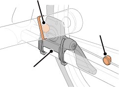
Wheel
magnet
Speed (cadence) sensor
Mounting on bottom of chain stay
Speed (cadence) sensor
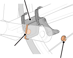
Cadence magnet
Wheel magnet
Caution
If the speed (cadence) sensor is mounted on the bottom of the chain stay rather than on the top, the adjustment range between the sensor and the magnet will be narrower.
* Mounting procedures give instructions for mounting on the top of the chain stay.
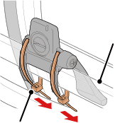
1. Temporarily attach the sensor to the left chain stay.
(1) Loosen the sensor screw using a Phillips screwdriver and check that the sensor arm moves.
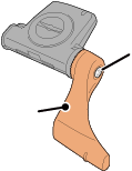
Sensor arm
Sensor screw
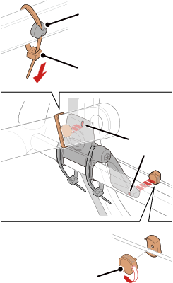
(2) Attach the sensor rubber pad to the sensor.
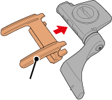
Sensor
rubber pad
(3) Refer to the illustration and temporarily attach the sensor to the left chain stay with nylon ties.
left chain stay
Nylon tie
Caution
Do not fully tighten the nylon ties. Once the nylon ties are fully tightened they cannot be removed.
2. Temporarily attach the magnet.
Inside of the crank
Cadence magnet
Spoke
Nylon tie
Sensor zone
Wheel magnet
(1) Using a nylon tie, temporarily attach the cadence magnet to the inside of the left crank arm so that it faces the cadence sensor zone.
(2) Rotate the sensor arm and temporarily attach the wheel magnet to a spoke facing the speed sensor zone.
* If the sensor cannot is not positioned so that both magnets (speed and cadence) pass through their respective sensor zones, reposition the sensor and the magnets so that each magnet passes through its sensor zone.
3. Adjust the gap between the sensor zone and the magnet.
(1) Tilt the sensor so that the gap between the cadence magnet and the cadence sensor zone is approximately 3 mm, then fasten the sensor securely with nylon ties.
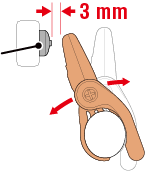
Cadence magnet
(2) Rotate the sensor arm so that the gap between the wheel magnet and the speed sensor zone is approximately 3 mm, then tighten the sensor screw securely.
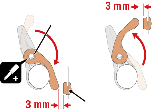
Wheel magnet
Sensor screw
4. Secure all parts.
Tighten the sensor's nylon ties, the sensor screw, and the magnets, and check that they are not loose.
Trim off the excess nylon tie.
* If using pedals with steel axles, the cadence magnet can be attached magnetically to the pedal axle. In this case, remove the adhesive tape from the magnet and do not use the nylon tie.
Copyright © 2021 CATEYE Co., Ltd.